Nickel and Dime Pitches
This article was written by Terry Bahill - Dave Baldwin - Alan Nathan
This article was published in 2006 Baseball Research Journal
The cover of a baseball comprises two strips of leather (identical dog bone–shaped geometrical figures called ovals of Cassini) stitched together with a single continuous red seam. The appearance of that seam during a pitch can provide information about the ball’s spin characteristics, which in turn might make the behavior of the pitch predictable. Therefore batters, catchers, and pitching coaches look for the seam spin pattern in order to evaluate a pitch. A spinning pitch (i.e., one that is not a knuckleball) might display one of three patterns due to the rotation of the seam: a distinct dot, a circle of variable size and sharpness, or two fuzzy bands girding the ball (Bahill et al., 2005).
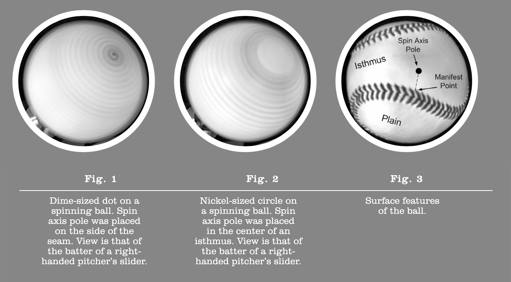
Pitching coaches often refer to the appearance of sliders and curves in terms of two U.S. coins—the dime and the nickel. The monetary designations allude to the dime-sized red dot (Fig. 1)1 or nickel-sized red circle (Fig. 2) that is observable on some sliders and curveballs. When visible, these features can be seen on the face of the slider, from the side of the overhand curveball, or from above the sidearm curve.
Generally, coaches and players assume the dot indicates a fast-spinning pitch (sometimes called a “tight” spin) with a consequential large deflection; the circle or the pattern of indistinct bands is believed to signal a slower-spinning pitch with inferior deflection. Are those assumptions valid?
In this paper we will attempt to answer that question in a series of three steps. First, we present models that describe how the various orientations of spin axis and seam might result in the visible spin patterns of curveballs and sliders. Then for each of those two pitches, we describe how the grip and release of the ball could produce poor deflection. Finally, we speculate as to how these inadvisable grip and release features might have become associated with a circular or banded spin pattern.
Plausible Explanations of the Dot and Circle Features
The dot appears on the dime curve or slider if one of the ball’s spin-axis poles is located on a seam. The farther the pole is shifted from the seam, the less distinct the dot becomes. We define the manifest point to be the point on the seam that is nearest the pole (Fig. 3). With a pole displacement of a few millimeters, a small, fuzzy, reddish circle can be discerned due to the manifest point rotating around the pole. Shifting the pole into the large plain of one of the Cassini ovals causes the circle to widen to an encompassing band. If the pole is located near the center of a plain, neither dot nor circle can be discerned.
A possible cause of a distinct nickel-sized circle on a pitch would be the location of the spin-axis pole near or at the midpoint of the narrow gap or isthmus between two of the plains (as shown in Fig. 4b). The distance across the seamless part of the isthmus is approximately 22 mm, nearly equal to the diameter of a nickel (~21 mm). The seam spinning rapidly around the mid-isthmian point would produce a reddish circle with an internal area about the size of a nickel. In contrast to the circles caused by a pole migrating into a plain, this circle would be quite distinct and invariable in size. Note that the circular pattern around a mid-isthmian pole would be reinforced by having two manifest points rotating about the axis.
Another possible cause of a circle on a nickel pitch would be a rotation of the dot, in a phenomenon called precession. This is a “wobble” or gyration of the spin axis about a secondary axis. If the dot at the end of the spin axis rotates, it circumscribes a small circle. The precession can rotate in the opposite direction or same direction as the spin.
Precession is a common feature of spinning objects. The term was first used by Hipparchus of Nicea in 130 B.C. when he described the effects of the wobble of the earth’s spin axis. Precession is also the basis of the behavior of a toy top, a gyro- scope, and a boomerang. In all cases, precession is caused by a secondary torque perturbing a spinning body.
Although the rotation of a manifest point or the precession of a pole might cause the appearance of the nickel-sized circle, this pattern does not necessarily indicate a reduced magnitude of spin or deflection. Note that the dot and circular patterns shown in Figs. 1 and 2 occur on balls spinning at the same rate. In addition, the spin axis has two poles—a dot pattern might appear at one pole, while the opposite pole displays a circle or bands. Obviously, the ball would not have different spin and deflection rates at the two poles.
Precession could affect curveball quality by continuously shifting the angle of the spin axis during the ball’s trajectory, thereby continuously redirecting instantaneous deflection and reducing total effective deflection. However, one of us (Bahill) has calculated that this reduction is insignificant.
Our approach to elucidating the assumed relationship between the circle and poor deflection, therefore, will be to present explanations coaches and pitchers have given us describing how grips and releases of pitches might have detrimental effects on deflection, and then to suggest how these manipulative flaws might yield the circular pattern.
Possible Pitch-Release Mechanics of the Nickel Curveball
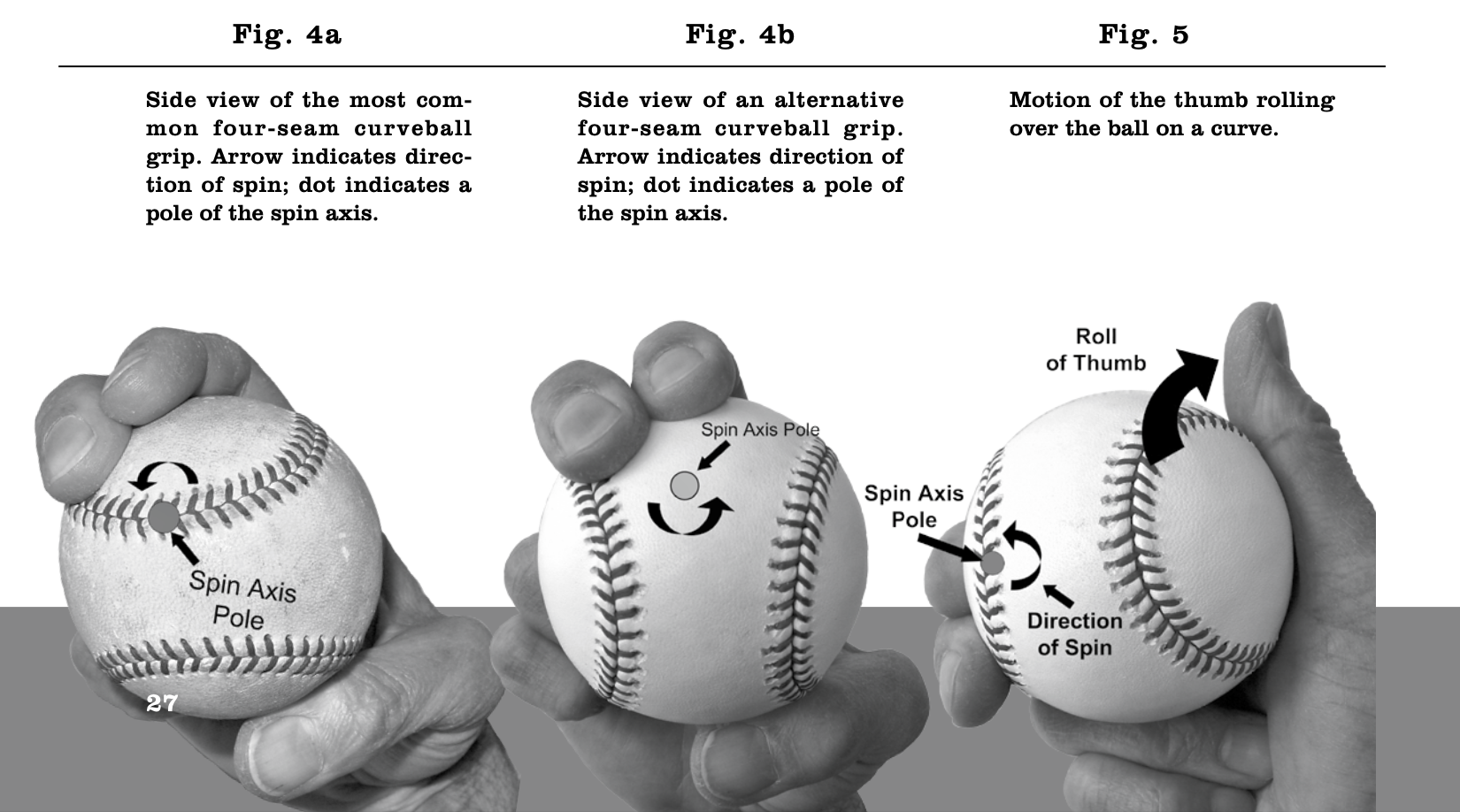
As Sal Maglie has described the release of the curveball from an overhand delivery, it is “thrown with a strong downward snap of the wrist and released between the thumb and the forefinger” (Terrell, 1958). The torque action of the first and second fingers and the ball’s forward linear momentum are translated into angular momentum as the ball rolls off the side of the forefinger, generating the curveball’s spin (topspin for an overhand pitcher). If the pitcher uses the more common of two possible four-seam grips for the curve (see Fig. 4a and Bahill et al., 2005), then the spin axis is set so that one pole is located on or very near the seam at a point directly distal to the fingertip of the index finger. With proper release, this might produce the visual effect of a dime curveball.
A slow spin (and consequent poor deflection) of a curve could be caused by a failure of the pitcher to snap the wrist hard just prior to release. Slow wrist action results in a weak torque applied to the ball by the fingers, producing insufficient angular momentum. This is probably one of the more common causes of poor deflection of the curve, but whether a reorientation of the spin axis occurs to create a nickel pattern must be the subject of further investigation.
A second possible cause of a poor curve is an overly active thumb. For the pitcher to get a rapid spin on the curve, the thumb should be directly behind the ball at the release. Most pitchers nudge the ball a bit with a little flick of the thumb—as long as the thumb stays behind the ball, it will not interfere with the spin.
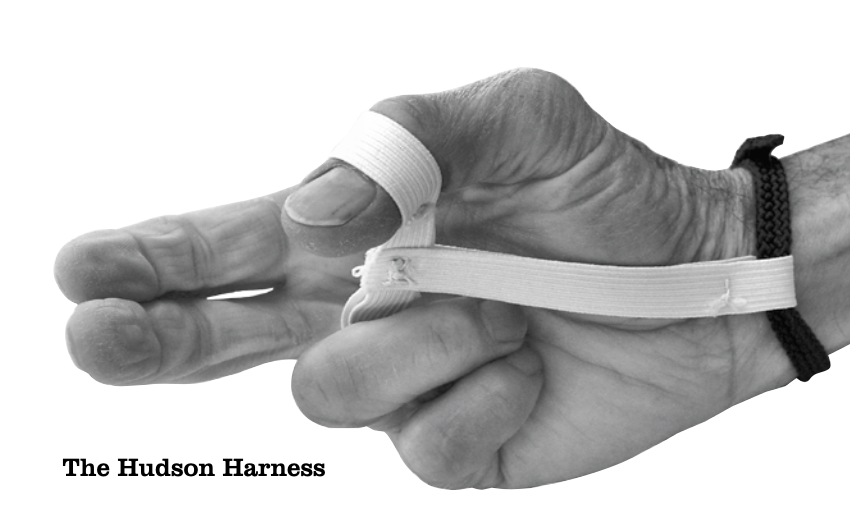
Sometimes the flick is exaggerated, however, and the thumb pivots upward and to the right (for a right-handed pitcher), as shown in Fig. 5. When Sid Hudson was the pitching coach of the Washington Senators during the 1960s he invented a device that pitchers called the “Hudson Harness.” It is a strap to be worn in practice as an aid in training pitchers to develop a faster spin and greater deflection of the curve. Hudson writes, “Most all pitchers coming out of high school will try to roll their thumbs over the top of the ball [as they release a curveball]. This is incorrect.”
An elastic band on Hudson’s device holds the thumb behind the ball, preventing the thumb roll. He has made this gadget for a large number of major league pitching coaches, so its use has been widespread in pro ball. After Hudson retired in 1986 from the Texas Rangers, where he had been pitching coach and then scout, he coached at Baylor University for six years and used the harness with great success.
According to Hudson, his device is designed to “keep the thumb from rolling over the top of the ball so that the ball will have more spin on it . . .” Although pitchers develop the thumb-rolling habit in their efforts to increase the ball’s spin rate, the errant thumb’s energy could be interfering with the spin somehow, thereby reducing deflection.
The rolling thumb applies torque to the right half of the spin axis at about a 15 to 20 degree angle to the direction of spin (see Fig. 5). Such a force applied asymmetrically to the axis of a spinning sphere might twist the axis into a wobble, or it might move an axis pole away from the seam. A nickel pattern could result in either case. Precession could produce poor deflection by redirecting spin momentum; alternatively, spin and deflection could be reduced by resistive friction of the thumb. In these models, the size of the circle on a nickel curveball and the quality of the pitch would be variable, depending upon the force applied by the thumb.
A third possible explanation for the nickel curveball is based on the position of the first and second fingers as they roll off the ball. If these fingers are on the side of the ball rather than the front at the moment of release, the pole could move farther from the fingertips—into the isthmus or the plain. The spin axis is not perpendicular to the trajectory of the pitch in this case, so the Magnus force (and, consequently, the magnitude of deflection) is reduced accordingly (see Adair, 2002, for an explanation of the Magnus force). This could result in the appearance of a nickel-sized circle and a poor curveball.
A fourth explanation for the nickel pattern on the curve involves the grip. The four-seam curveball can be gripped with either of two orientations. The grip shown in Fig. 4a seems to be the more common, but the ball could be rotated horizontally 180° (Fig. 4b), so that the index and second fingers are placed alongside the seam in such a way they point at an open end of an isthmus. The axis pole then occurs within the isthmus, creating the nickel aspect. This is true for several other possible curveball grips as well. The spin rate will be unaffected by the location of the axis pole, however, so a high-quality curve could result.
Possible Pitch-Release Mechanics of the Nickel Slider
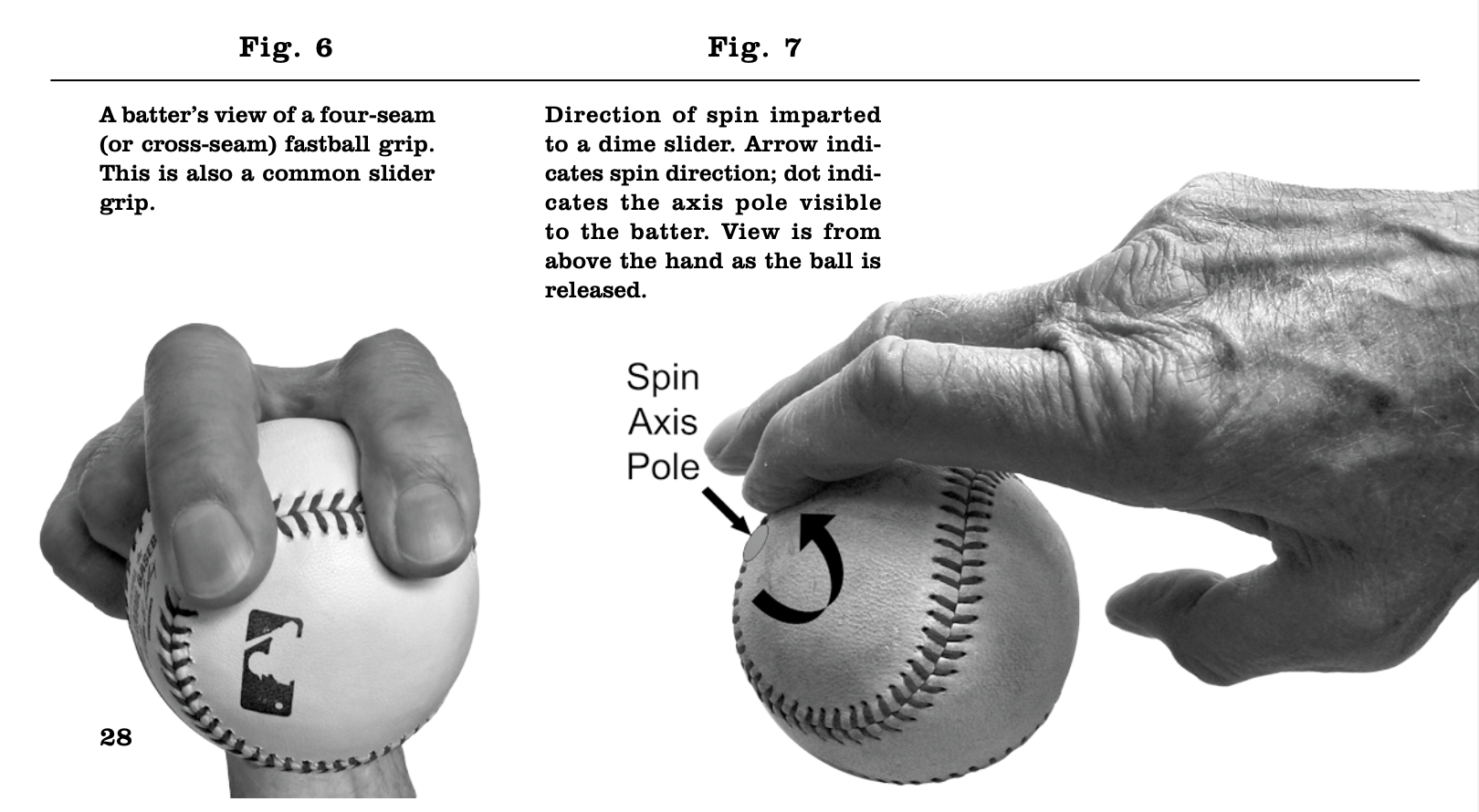
Sometimes the slider is thrown with a four-seam fastball grip (Fig. 6), because pitchers consider the slider to be a modified fastball, and because they avoid changing their grips any more than necessary. With the ideal release from this grip, the slider’s spin axis pole that is visible to the batter will be located on the ball’s seam (Fig. 7). This point on the seam would form the dot that identifies a dime slider.
Hudson has specified that his device is not appropriate for training a pitcher to throw a slid- er; the nickel slider and nickel curve might be caused by different errors in the release of the ball. To determine the cause of a poor slider, we interviewed four former major league pitchers— Dick Bosman, Bob Humphreys, Jim Kaat, and Ken Sanders (Kaat is left-handed; the others are right- handed). No pitchers possessed better sliders during the 1960s and ’70s.
All of these pitchers stressed that the ball must be thrown with good arm speed. The first and second fingers must be on top of the ball; the release point of the slider is slightly off-center, however. To ensure proper release, Humphreys (who learned to throw the slider from Frank Lary when they were teammates on the Tigers) says he concentrated on putting pressure on the right front corner of the ball. As a result of this pressure, the last part of his hand to touch the ball was the thumb-side edge of the index finger’s tip. The ball left his hand with the spin axis assuming an oblique angle to the forward direction of the pitch (see Fig. 7). Three of our interviewees reported that throwing sliders caused blisters or calluses on the thumb side of the index finger’s tip.
Pitchers often create a problem when they try to increase the spin rate of the slider—they have a tendency to throw a hybrid between the fastball and curve. On this point Sanders states, “When you break your wrist, it creates a bad slider,” and Bosman explains, “If the hand rolls over on the ball, the slider will be lazy—the spin is too slow.” Humphreys writes that a major problem occurs when the “hand gets around the side of the ball, instead of staying on top and throwing right-front corner.” Kaat states, “Too many pitchers today throw the slider like they’re ‘turning a door knob’. . . bad for the elbow and doesn’t have much ‘bite’ to it.”
As in the curveball, the spin of the slider is created by the friction of the index and second fingers. If these fingers stay on top of the ball, as recommended by our interviewees, an effective slider is produced with its spin axis at an approximate 60 degree angle to trajectory to give the “sliding” effect. When the wrist rolls to the outside of the ball, the spin axis is shifted so that it is more nearly parallel to the trajectory. If the four-seam fastball grip is used, this shift moves the leading axis pole away from the seam, which might result in a nickel-sized circle. The Magnus force and deflection of the pitch are reduced because the hand rolling over the ball produces a slow spin with the axis shifted toward the direction in which the ball is moving.
As with the curveball, a number of different grips have been used for the slider. We do not know which grip is most popular. Some of these grips could produce a dot; some will not, no matter how well the pitch is released or how effective the pitch might be.
Summary
Coaches and players are in general agreement that spin rates and deflections of the nickel curve and nickel slider are considerably reduced compared to the dime versions of these pitches. As shown in our figures, the nickel pattern does not necessarily indicate a slow spin and poor deflection, however. The circular features that appear on nickel pitches might be caused by precession of the spin axis or by a shift of an axis pole to a position some distance from the seam, such as the mid- point of an isthmus. We have presented pitchers’ and coaches’ explanations of how the hand might create poor pitch quality, and we have suggested how the described pitch grips and release mechanics might create nickel patterns on pitches.
We conclude that the circular pattern seen on a nickel pitch results from certain orientations of the seam relative to the spin axis. Whether or not this pattern is associated with a pitch of poor quality depends on the pitcher’s grip and release of the ball.
DAVE BALDWIN pitched for the Washington Senators, Milwaukee Brewers, and the Chicago White Sox in the 1960s and 70s. Later, he earned a Ph.D. in genetics and an M.S. in systems engineering from the University of Arizona.
TERRY BAHILL is a Professor of Systems Engineering at the University of Arizona in Tucson. He received the Sandia National Laboratories Gold President’s Quality Award. He is a Fellow of the Institute of Electrical and Electronics Engineers (IEEE) and a Fellow of the International Council on Systems Engineering (INCOSE).
ALAN NATHAN, professor of physics at the University of Illinois since 1977 and a fellow of the American Physical Society, is the author of more than 80 publications in scientific journals. His research specialty is experimental nuclear/particle physics. He has written numerous papers on the physics of baseball, primarily on the physics of ball–bat collision and on baseball aerodynamics. His website devoted to the physics of baseball is www.npl.uiuc.edu/~a-nathan/pob.
Acknowledgments
We are grateful to Dick Bosman, Sid Hudson, Bob Humphreys, Jim Kaat, and Ken Sanders for providing their cooperation, advice, and valuable information to make this article possible. We thank Sid Hudson for sending us an example of his device. Also, we thank Zach Bahill for photographing the pitch simulations shown in Figs. 1 and 2; for all other figures the photographer was Burgundy Featherkile. Additional thanks go to Eric Sallee for his help with experimentation on spin axis angles.
Sources
Adair, R. K. The Physics of Baseball, 3rd ed. New York: HarperCollins, 2002.
Bahill, A.T., D.G. Baldwin, and J. Venkateswaran. “Predicting a Baseball’s Path,” American Scientist, 93(3):218–225 (May–June 2005).
Terrell, R. “Sal Maglie on the Art of Pitching,” Sports Illustrated, 8(11): 34–45 (March 17, 1958).
Notes
1 To create the simulations shown in Fig. 1 and Fig. 2 we drilled a hole in a regulation baseball and inserted a four inch bolt. The bolt was chucked in a drill and spun at a rate of 250 rpm. The bolt is the spin axis, which defines the pole. The shutter speed was 0.5 seconds and the f-stop was set at 5.6. We have shown the batter’s view of a right-handed pitcher’s slider.

